Readiness Page
The following article is based on 193377 Revision B software, for older revisions scroll to the bottom of this page.
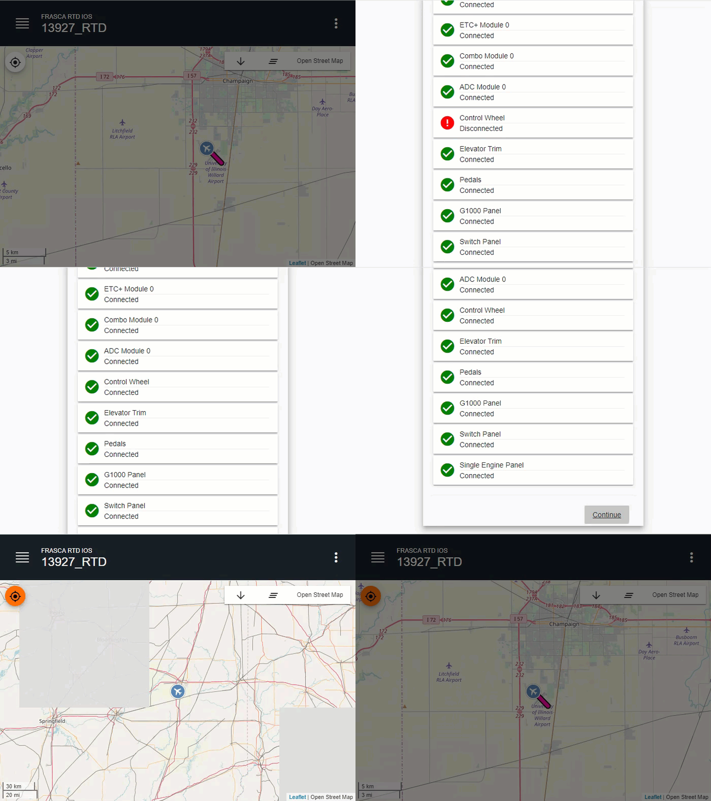
The Readiness page displays automatically when a system software or hardware component failure occurs on the RTD.
- Red indicates a component is failed or offline.
- Green indicates a component is running correctly.

The following optional components are displayed on the Readiness page.
- Raptor Host software processes all the flight computations and manages the sound functions. Host software communicates with all software components installed in the RTD.
- Griffon Host software manages the hardware I/O (input/output) and Garmin avionics. Griffon Host software communicates with all CAN devices by sending packets over Ethernet to the ETC+ (Ethernet to CAN) Module.
- Prepar3D is responsible for generating the out-of-the-cockpit view for the display system.
- CGI (Computer Generated Instruments) software generates the graphics for standby instrumentation on the G1000 model, and the instrumentation for the steam gauge model.
- RealityXP is the Garmin GNS430 Rehost software which manages the GNS430 I/O (input/output).
- ETC+ Module acts as a gateway providing an interface between Ethernet and CAN Bus. The ETC+ Module is the interface between the Host software and the CAN Bus.
- Combo Module is typically used for controlling annunciators and solenoids, reading potentiometers for lighting bus dimmers or for control positions, as well as reading switch positions.
- ADC Module or Analog to Digital Converter Module is typically used to read potentiometers for control positions.
- RTD Assemblies on the RTD Readiness page include the following optional components.
- Instrument Panel
- Avionics Panel
- G1000 Panel
- Switch Panel
- Single Engine Panel
- Pedals
- Control Wheel
- Elevator Trim
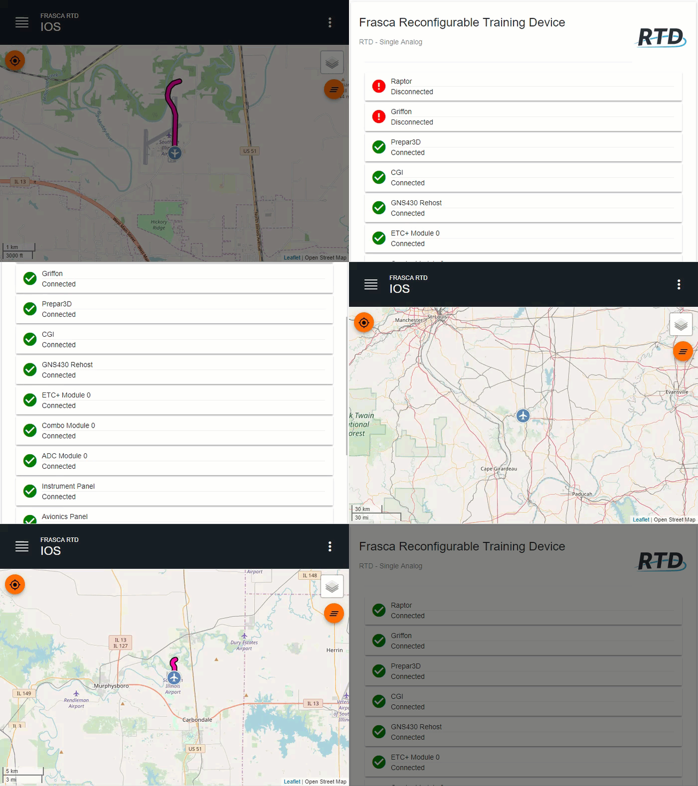
The Readiness page displays automatically when a system software or hardware component failure occurs on the RTD.
- Red indicates a component is failed or offline.
- Green indicates a component is running correctly.

The following optional components are displayed on the Readiness page.
- Raptor Host software processes all the flight computations and manages the sound functions. Host software communicates with all software components installed in the RTD.
- Griffon Host software manages the hardware I/O (input/output) and garmin avionics. Griffon Host software communicates with all CAN devices by sending packets over Ethernet to the ETC+ (Ethernet to CAN) Module.
- Prepar3D is responsible for generating the out-of-the-cockpit view for the display system.
- CGI (Computer Generated Instruments) software generates the graphics for standby instrumentation on the G1000 model, and the instrumenatation for the steam gauge model.
- RealityXP is the Garmin GNS430 Rehost software which manages the GNS430 I/O (input/output).
- ETC+ Module acts as a gateway providing an interface between Ethernet and CAN Bus. The ETC+ Module is the interface between the Host software and the CAN Bus.
- Combo Module is typically used for controlling annunciators and solenoids, reading potentiometers for lighting bus dimmers or for control positions, as well as reading switch positions.
- ADC Module or Analog to Digital Converter Module is typically used to read potentiometers for control positions.
- RTD Assemblies on the RTD Readiness page include the following optional components.
- Instrument Panel
- Avionics Panel
- G1000 Panel
- Switch Panel
- Single Engine Panel
- Pedals
- Control Wheel
- Elevator Trim
